
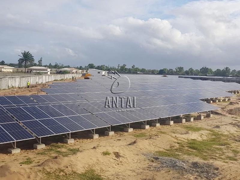
Bifacial modules capture irradiance reaching both front and rear surfaces, but the rear side sees a complex field of reflected light and structural shadow. Rows, rails, posts, torque tubes, cable trays, vegetation, and neighboring modules can all reduce or redistribute the irradiance available to rear cells.
Effective ground mount solar racking treats bifacial gain as a system-design problem involving geometry, albedo, structure, terrain, wiring, and maintenance. Antaisolar provides customized ground configurations for different land uses, giving designers an opportunity to coordinate structural requirements with rear-side exposure rather than evaluating modules alone.
Mapping the Sources of Rear-Side Loss
Rear irradiance begins with light reflected from the ground and nearby surfaces. Soil color, gravel, vegetation, snow, moisture, and seasonal change affect albedo. Measurement or justified site assumptions are preferable to a generic value, particularly when an energy model relies on a large bifacial contribution.
Structural members create direct shadow and may also block diffuse light from portions of the sky. The importance of a rail, post, or brace depends on its width, distance from the module, orientation, repetition, and position relative to cells. Narrow components can still create localized mismatch when aligned repeatedly over the same cell areas.
Row spacing and height control how much reflected light reaches the rear surface. Greater clearance can increase the rear-side view factor to the ground, while wider pitch reduces inter-row obstruction. These changes consume land and may increase structural demand, cable length, or foundation cost, so optimization should use project economics rather than maximum theoretical gain.
Antaisolar’s portfolio includes conventional arrays, vertical mounting, agrivoltaics, carports, and fishery-PV structures. Each arrangement creates a different irradiance environment. A useful comparison models the chosen module, mounting geometry, surface conditions, and operating scenario instead of applying one bifacial factor across all forms.
Designing Structure and Services Around Bifacial Modules
Component placement can reduce persistent rear shading. Rails, purlins, braces, clamps, and cable routes should avoid the most sensitive cell regions where practical. Symmetrical support and distributed obstructions often produce more manageable irradiance patterns than a few wide shadows concentrated behind active areas.
Cable management deserves early coordination in ground mount solar racking. Loose loops or trays located close to the backsheet can create irregular shade, interfere with airflow, or complicate cleaning. Defined routes, controlled sag, UV-resistant attachments, connector support, and accessible service loops improve both energy performance and reliability.
Antaisolar provides tailored engineering based on terrain, installation efficiency, and long-term performance. Bifacial-focused submittals should add module clearance, structural-shadow geometry, cable routing, row pitch, tilt, and surface assumptions to the usual load calculations and fabrication drawings.
Energy analysis should use three-dimensional geometry where structural shading is material. The model can compare hourly rear irradiance, mismatch, self-shading, soiling, and seasonal albedo. Field validation with reference sensors or calibrated measurements helps identify whether assumed gain survives construction tolerances and actual ground conditions.
Preserving Rear-Side Access During Operation
Vegetation growth changes albedo and can directly shade low module edges. Management plans should define height limits, mowing or grazing methods, herbicide restrictions, drainage treatment, and access around piles. Agrivoltaic use adds crop or livestock requirements that must be represented in the energy and maintenance plan.
Soiling can accumulate differently on front and rear glass, particularly near roads, bare soil, agricultural activity, or water. Cleaning frequency should follow measured loss and local economics. The structure needs sufficient access for safe cleaning without damaging cables, coatings, vegetation controls, or module backsheets.
For long-term operation, Antaisolar uses optimized ground structures and offers local installation and commissioning support. Handover should include as-built geometry, cable-route records, surface treatment, vegetation assumptions, and inspection points so the intended rear-side environment can be maintained.
Reduced shading is not the result of a single narrow rail or elevated row. It comes from coordinated optical modeling, structural design, cable discipline, land treatment, installation quality, and operating practice. Project teams that preserve those interfaces can turn modeled bifacial gain into more dependable lifetime energy.